

How to Plan Two-Depth Artwork for Three-Ply Engraving Sheets
How to Plan Two-Depth Artwork for Three-Ply Engraving Sheets
Three-ply engraving artwork can reveal two contrasting colors from one processing face. Reliable production depends on mapping every graphic element to the correct depth, testing the actual material and keeping the approved file, sample and setup under one revision.
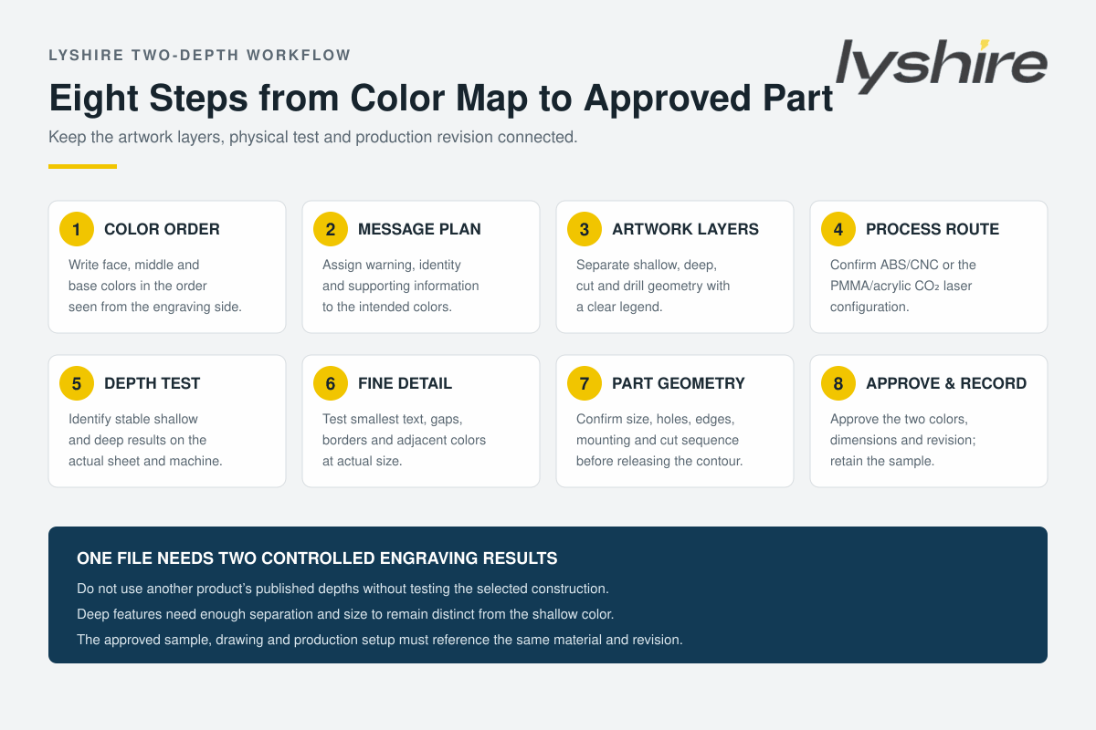
Quick answer: write the layer colors in order from the engraving face downward, assign each message to the intended revealed color, separate shallow and deep artwork layers, keep cutting and holes independent, confirm the material/process route, test both depths and the smallest detail, and approve one representative finished part before batch production.
First confirm what “three-ply” means for the selected sheet
Industry terminology is not perfectly uniform. Rowmark’s glossary describes two-ply and three-ply substrates in terms of contrasting cap layers and core relationships, while its LaserMax Tri-Layer product is specifically described as a film, cap and core. Other three-layer engraving plastics may use another construction. Therefore, the phrase three-ply engraving sheet is not enough to define the visible color order or processing direction.
Write the construction from the working face downward. For the white/red/black example in this guide, the order is white face, red middle layer and continuous black base. A shallow pass removes the white face and reveals red. A deeper pass continues through the red layer and reveals black. If the order were black/red/white, the same artwork would produce a completely different result.
Ask for a physical cross-section, color swatch or approved sample and identify the engraving side. Do not infer the order from a small thumbnail, product code or list of three colors.
Start with the message hierarchy—not the machine depth
Before assigning process settings, decide what each color means in the finished design. The middle color may carry a warning word, status band or key symbol, while the base color carries equipment identification, instructions or supporting text. This creates a visual hierarchy without paint filling or separately applied pieces.
Color meaning is project-specific. A red middle layer does not automatically make a sign compliant with a safety standard. The designer or equipment builder must define required wording, symbols, color use and placement according to the applicable standard and risk assessment.
Use the PDF proof to show the expected final colors, not only the artwork layer colors. Operators should be able to compare the screen preview, physical sheet and finished sample without interpreting an undocumented code.
Create an explicit color-to-depth map
| Artwork group | Expected visible result | Production meaning |
|---|---|---|
| FACE / UNENGRAVED | White | Original surface remains; no engraving operation |
| SHALLOW / COLOR 2 | Red | Remove the white face and stop within the red middle layer |
| DEEP / COLOR 3 | Black | Remove the white and red layers and expose the continuous black base |
| CUT / OUTER PROFILE | Finished edge | Separate contour operation; not a display color |
| HOLES / SLOTS | Open geometry | Drill or cut-through operation with controlled size and position |
| NOTES / DIMENSIONS | Not processed | Production information excluded from engraving output |
Name the layers by function rather than by software color alone. “SHALLOW_RED” and “DEEP_BLACK” communicate more than “Layer 1” and “Layer 2.” Add a legend showing the required finished color, expected depth group and material reference.
Build clean artwork at actual size
Prepare the three-ply engraving artwork at 1:1 scale, state whether dimensions use millimetres or inches, and include the finished width and height on the proof. Convert approved production text to outlines while retaining a separate editable master. Remove duplicate paths, open contours and hidden geometry that could run twice or enter the wrong depth group.
Keep shallow, deep, cut, hole and note layers separate. If a graphic contains both red and black features, split the objects rather than using an appearance effect that may be flattened or reinterpreted during export. Check that clipping masks, compound paths and reversed shapes remain correct in the production software.
For detailed artwork preparation principles, review the LYSHIRE precision-engraving artwork guide and supply a human-readable PDF proof alongside the production vector file.
Select the material and processing route together
Trotec confirms that laserable plastics are available in one-, two- and three-layer constructions and describes modified-acrylic two- to three-layer sheets for laser engraving and cutting. Rowmark’s LaserMax Tri-Layer is a product-specific impact-acrylic construction with published shallow and deep engraving depths. These figures show the concept, not a universal setting for every supplier.
LYSHIRE’s standard ABS configuration belongs to the CNC/rotary route. CO2 laser projects should use the separate PMMA/acrylic-based configuration that has been selected for laser processing. Do not test a standard ABS sheet with copied laser parameters merely because another three-ply product is laserable.
State the machine type in the inquiry and review the LYSHIRE processing system. If the sheet will be supplied as finished parts, provide the artwork and geometry so the appropriate fabrication route can be evaluated.
Determine shallow and deep results with a test strip
A two-depth job needs two stable visual results. Create a test strip that moves gradually from insufficient face removal through a clean middle-color reveal and then toward the base color. The acceptable shallow window should expose the middle color consistently without showing the base through thin areas.
Next, establish the deep result. It must remove the first two layers and reveal the base cleanly without cutting unnecessarily far into the sheet. Excessive depth can enlarge features, increase heat or cutter load, and make adjacent shallow regions harder to control.
Record the accepted shallow and deep settings with the exact material, thickness, batch or sample reference, equipment, lens or cutter and date. Published depths from another product can be useful context but must not replace testing.
Design for the smaller process window
The shallow layer may be thin, while the deep pass must travel farther before the base color appears. This difference affects small text, narrow gaps and closely adjacent colors. A feature that engraves clearly in red may widen, soften or merge when processed to black at the deeper setting.
Test the smallest red text and the smallest black text separately. Also test red and black features placed next to each other, tight inside corners, thin borders, reversed text and small islands. Leave enough separation so the deep pass does not disturb a neighboring shallow feature.
There is no single minimum character height or stroke width for every three-ply engraving sheet. The material structure, face thickness, middle-layer thickness, laser spot or cutter tip, depth, focus, runout and artwork all influence the result.
Plan CNC and rotary tools for both depths
For mechanical engraving, cutter-tip geometry determines how a channel widens as it goes deeper. A V-shaped cutter, for example, naturally produces a wider opening at greater depth than at a shallow pass. This must be considered when the same typeface appears in both middle and base colors.
Confirm tool sharpness, spindle condition, sheet hold-down, Z reference and chip removal. A small change in sheet height can shift a feature from red toward black, particularly where the acceptable middle-layer window is narrow. Test several positions across the sheet if flatness or bed condition may affect effective depth.
Engrave the shallow and deep information while the part is still well supported whenever the geometry and CAM strategy allow. Holes and outer contours can then be completed according to the verified sequence, with small-part retention planned before the final cut.
Plan laser artwork as separate operations
On the appropriate PMMA/acrylic-based laser configuration, shallow and deep artwork should be assigned to separate operations or parameter groups. Do not rely on subtle screen colors without a layer legend. Confirm that vector cutting contours cannot accidentally receive an engraving setting, and vice versa.
Depth may be adjusted through controlled combinations of power, speed, resolution, passes and focus according to the equipment and selected material. Avoid presenting one parameter set as universal. Inspect for residue, excessive heat, surface damage and incomplete middle- or base-color exposure.
If multiple passes are used, check alignment and whether the later pass affects adjacent shallow artwork. A representative sample should contain the same mix of small, large, shallow and deep features as the real job.
Control variable data and repeated layouts
Three-ply tags often combine fixed warning graphics with variable equipment numbers, locations or serial data. Define which variable fields use the middle color and which use the base color. A structured spreadsheet should contain one row per part, a unique ID, exact text and the intended artwork group.
Generate a proof that shows the finished red and black result for representative records. Check the longest value, smallest text and any characters outside the primary language. Reconcile the row count, requested quantity and packing list before production.
Do not manually retype corrections at the machine. Update the controlled source, issue a new revision and regenerate the production file and proof.
Integrate holes, profiles and mounting
The drawing should define finished dimensions, thickness, corner radius, hole diameter and centre positions, slots, cutouts, edge requirements and mounting. Keep cut-through geometry separate from the two engraving depths. A hole should not be confused with a black circular graphic, even if both appear dark in a preview.
If adhesive backing is required, specify the installation substrate, texture, curvature and environment. Mechanical holes and adhesive can affect usable margins and the spacing of the shallow and deep artwork. Check fastener-head clearance and avoid placing critical text too close to a cut edge.
Approve the most demanding sample
The sample should not contain only large text. Include the smallest shallow feature, smallest deep feature, closest red/black spacing, largest filled area, relevant holes, outer contour and intended mounting method. Inspect color separation, residue, depth, dimensions, edges and surface condition.
Record the material color order, construction, thickness, artwork revision, shallow/deep settings and approved sample date. If the color order or material model changes, repeat the test rather than carrying over the old settings.
For production inspection, compare parts against the approved sample under consistent lighting. Check that shallow features remain the middle color and deep features consistently reach the base without unintended breakthrough.
Common failures and corrective checks
| Observed problem | Items to review |
|---|---|
| Shallow red areas show black spots | Depth window, bed level, sheet flatness, focus or Z reference, tool condition and middle-layer consistency |
| Deep black areas still contain red | Deep setting, passes, cutter geometry, focus, residue and exact material structure |
| Black text becomes wider than red text | Deep-pass geometry, V-cutter width, laser spread, font weight and sample comparison |
| Red and black features merge | Spacing, deep-feature expansion, artwork overlap, process order and minimum-detail test |
| Wrong colors appear in production | Face direction, color order, artwork layer mapping, material code and operator legend |
| Repeat order looks different | Material model, batch, settings record, tool or optic, sample revision and machine condition |
Design boundary: a three-ply sheet does not automatically improve precision or durability. Successful two-depth output depends on the exact construction, material route, artwork spacing, controlled processing and approved sample.
RFQ checklist for two-depth three-ply projects
Send LYSHIRE the color order from the engraving face downward, material route, thickness, full-sheet or finished-part format, artwork with shallow/deep/cut layers, PDF color proof, smallest text and gap, dimensions, holes, mounting, environment, variable-data table, quantity, sample approval and inspection requirements.
For custom color orders, nonstandard shapes or adhesive backing, see LYSHIRE custom applications. The technical team can review whether the requested structure and process route are suitable for sampling.
Frequently Asked Questions
Does every three-ply sheet reveal two colors from one side?
No. Industry terminology and construction vary. Confirm the exact layer order and engraving side for the selected product.
Can one engraving depth reveal both lower colors?
No. The middle and base colors require separate controlled results. The exact shallow and deep settings must be established on the real sheet.
Can published engraving depths be copied from another brand?
Use them only as background information. Layer thickness, material, machine, tool and desired result vary, so a representative test is required.
Should shallow and deep artwork be placed on separate layers?
Yes. Keep shallow, deep, cutting, holes and production notes clearly separated and provide a color/depth legend.
Can LYSHIRE three-ply sheets be laser or CNC processed?
Choose the correct construction. Standard ABS belongs to the CNC/rotary route; CO2 laser projects should use the separate PMMA/acrylic-based configuration.
What should the approval sample contain?
Include the smallest shallow and deep features, closest two-color spacing, relevant holes, outer contour and intended mounting method.
Request a Three-Ply Artwork Review
Send LYSHIRE the color order, shallow/deep artwork, material route, dimensions, smallest detail and quantity. The technical team can review the structure and representative sample plan.
Contact LYSHIREThree-layer material references: Trotec two- to three-layer laser plastics, Rowmark LaserMax Tri-Layer specifications, Rowmark Tri-Layer construction description and Rowmark material terminology glossary.