
How to Calculate Laser Engraving Laminate Sheet Yield
Material Yield and Job Planning
How to Calculate Laser Engraving Laminate Sheet Yield
The number of finished labels produced from one laser engraving laminate sheet cannot be calculated accurately from area alone. Real yield depends on usable sheet dimensions, part geometry, outer margins, tested kerf and spacing, layout direction, finish orientation, fixtures, engraving zones and production allowances.
Direct answer: start with the measured usable sheet area—not only the catalog size. Add the required boundary margin and validated spacing to each part, compare both orientations, then deduct areas that cannot be used. Finally, convert the planned quantity into an expected acceptable output by allowing for setup pieces, inspection samples and project-specific losses.
Three Different Numbers
Do Not Confuse Area Ratio, Nested Quantity and Acceptable Output
Theoretical Area Ratio
Usable sheet area divided by one part’s area gives an upper mathematical limit. It ignores gaps, margins, irregular shapes and leftover strips.
Planned Nested Quantity
This is the number that fits in the approved layout after orientation, spacing, geometry and unusable areas are included.
Acceptable Production Output
This is the quantity expected to pass engraving, cutting, dimensional and visual inspection after setup and quality allowances.
Input Checklist
Eight Values Needed Before Calculating Sheet Yield
| Input | What to confirm | Typical planning risk |
|---|---|---|
| Usable sheet width and length | Measured production area after edge trimming, damage zones and machine limits. | Using nominal size can overstate output if sheet edges or the machine bed are not fully usable. |
| Finished part size | Final width, height, radius, holes, slots and dimensional tolerance. | Artwork size may differ from the required finished blank size. |
| Outer boundary margin | Space required for sheet placement, clamps, vacuum loss, edge variation or test cuts. | A zero-margin drawing may not be stable or repeatable on the real machine. |
| Part-to-part spacing | Validated distance considering kerf, heat, support and part removal. | Spacing that works on one machine or thickness may not transfer to another. |
| Orientation rule | Whether parts may rotate 90° or require one fixed direction. | Brushed, patterned or directional surfaces can make a high-count rotated layout unacceptable. |
| Geometry and common edges | Rectangles, mixed shapes, internal holes and whether shared cut lines are approved. | Complex outlines create unusable pockets; shared lines can change edge quality or part separation. |
| Process sequence | Engrave first or cut first, variable data order, registration and protective-film handling. | Small loose parts may shift if the sequence is not planned. |
| Production allowance | Setup coupons, inspection samples, retained samples, rejects and spare parts. | Ordering only the exact nested quantity leaves no protection for approval or unexpected loss. |
Simple Rectangular Grid
Start with a Transparent Formula
For identical rectangular parts arranged in one direction, a first grid estimate can be calculated as follows. Use one consistent unit, normally millimetres.
Columns = floor[(usable width − 2 × outer margin + spacing) ÷ (part width + spacing)]
Rows = floor[(usable length − 2 × outer margin + spacing) ÷ (part length + spacing)]
Grid quantity = columns × rows
Rows = floor[(usable length − 2 × outer margin + spacing) ÷ (part length + spacing)]
Grid quantity = columns × rows
Repeat the calculation after rotating the part 90°. If rotation is permitted, compare the two results. This formula is a planning screen, not a replacement for CAD nesting or a machine test. Mixed shapes, irregular outlines and shared cut paths require layout software and technical review.
Worked Example
The Same Part Can Produce Different Counts after Rotation
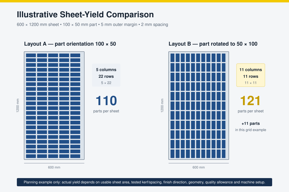
Assume a 600 × 1200mm usable sheet, a 100 × 50mm finished label, a 5mm outer margin and 2mm spacing. These values are illustrative only; they are not LYSHIRE’s universal cutting settings.
| Layout | Width calculation | Length calculation | Grid quantity |
|---|---|---|---|
| 100 × 50 orientation | floor[(600 − 10 + 2) ÷ 102] = 5 | floor[(1200 − 10 + 2) ÷ 52] = 22 | 5 × 22 = 110 |
| 50 × 100 orientation | floor[(600 − 10 + 2) ÷ 52] = 11 | floor[(1200 − 10 + 2) ÷ 102] = 11 | 11 × 11 = 121 |
Directional Surfaces
Brushed and Patterned Finishes Can Override the Highest Count
Matte solid-color laminate often allows more layout freedom, but brushed metallic, carbon-fibre, woodgrain and other directional finishes require a controlled visual direction. Rotating only some parts may cause finished labels installed beside each other to reflect light or display the pattern differently.
The job file should therefore record an orientation arrow or grain direction. If labels will be installed as one set, calculate yield using the required common direction even when a rotated layout produces more pieces mathematically.
For finish and construction options, review the LYSHIRE structure system and the laser engraving sheet range.
Count Is Not the Only Objective
A layout with more parts is not better if it creates inconsistent grain direction, weak holding tabs, heat concentration, unstable small pieces, difficult sorting or an unacceptable production sequence. Optimize acceptable output per sheet—not rectangles on a screen.
Kerf and Spacing
Measure the Actual Machine–Material Combination
Laser kerf is material removed along the cut path. It is affected by material construction and thickness, focus, lens, power, speed, beam condition and extraction. A value used for one laser or another sheet should not be inserted into production drawings without verification.
Cut a calibrated test shape in the selected laminate, allow the material to cool, then measure the finished piece and opening with suitable equipment. Use the result to compensate critical dimensions and to validate the minimum safe spacing between parts. Narrow kerf can support tight nesting, but spacing must also consider heat, sheet support, small-part movement, edge quality and removal from the bed.
From Layout to Purchase Quantity
Convert Planned Yield into a Sheet Requirement
- Approve the material: confirm PMMA/acrylic laser configuration, face/core colors, finish, thickness and usable sheet dimensions.
- Validate the part: test the smallest text, narrowest line, holes, corners and outside cut on the intended CO2 laser.
- Freeze the layout rules: record margins, spacing, rotation, grain direction, engraving order and cut order.
- Calculate the nested quantity: compare orientations and use CAD nesting for mixed or irregular shapes.
- Reserve non-saleable pieces: add setup coupons, first-article approval, inspection samples and retained samples.
- Add the agreed production allowance: base it on job complexity, prior records and quality risk rather than an automatic percentage.
- Round up to full sheets or packaging units: confirm whether excess acceptable parts should be supplied, retained or excluded.
Required sheets = ceiling[(required good parts + fixed sample/spare quantity) ÷ validated acceptable output per sheet]
Production Risks
Why Actual Yield May Be Lower Than the CAD Count
| Nominal sheet size used as usable area | Measure the actual approved working zone and deduct edge, fixture and machine restrictions before nesting. |
| Kerf not compensated | Test the selected laminate and settings, especially when finished dimensions, slots or mating parts are critical. |
| Parts move after cutting | Review cut sequence, vacuum or bed support, spacing, tabs where appropriate and whether engraving should be completed first. |
| Directional finish is mixed | Lock all artwork to the approved brushed or patterned orientation before calculating final quantity. |
| Variable data is mismatched | Link the nesting position, data file, inspection record and sorting method before processing serialized labels. |
| No allowance for approval pieces | Reserve setup, first-article, inspection and retained samples separately from the customer’s good-part quantity. |
RFQ Checklist
Information Needed for a Reliable Yield or Finished-Part Quote
- Material: laser engraving laminate product, face/core colors, finish and thickness.
- Sheet format: full-sheet size or required cut blank, plus usable-area restrictions.
- Finished drawing: dimensions, tolerance, holes, slots, radius, special outline and edge requirements.
- Artwork: fixed or variable text, minimum character size, line width, barcode or QR requirements.
- Direction: whether the surface, text or installation requires one orientation.
- Mounting: adhesive backing, holes, screws, rivets or another system.
- Quantity: required good parts, spare quantity, sample approval and packaging units.
- Delivery scope: full sheets, nested cut blanks or completely engraved finished parts.
LYSHIRE can discuss full sheets, cut blanks and finished identification parts through its custom application service.
Frequently Asked Questions
Laser Engraving Laminate Yield FAQ
Can sheet yield be calculated by dividing sheet area by part area?
That calculation gives only a theoretical upper limit. Actual yield must include usable sheet dimensions, margins, spacing, kerf, geometry, orientation, unusable zones and production allowances.
Should every label be rotated to increase the count?
No. Rotation is allowed only when brushed or patterned direction, artwork, holes, mounting, installation and customer specifications permit it.
What kerf value should be used for laser engraving laminate?
Use a value measured from the selected laminate on the intended machine with the approved focus and cutting settings. Do not assume one universal kerf for every material, thickness or laser.
How much spacing is required between laser-cut labels?
Spacing must be validated for the material, thickness, machine, support, heat input, part size and cut sequence. Tight nesting should not compromise edge quality or part stability.
Why can actual output be lower than the nesting software count?
The software count may exclude setup coupons, inspection samples, sheet-edge restrictions, movement, dimensional rejects, surface defects, sorting errors or other production losses.
What files should be sent for a finished-label yield calculation?
Provide a dimensioned drawing and vector artwork together with material, finish, thickness, quantity, tolerance, direction, variable-data, mounting and packaging requirements.
Layout and Quotation Review
Calculate Acceptable Output before Ordering Full Sheets
Send LYSHIRE your finished drawing, artwork, laminate structure, thickness, surface direction and required quantity. Our team can review the material route and provide full sheets, cut blanks or finished laser-engraved parts for qualified B2B projects.
Contact LYSHIRETechnical references: official sheet-size and material specifications from Rowmark LaserMax and Gravotech Gravoply Laser; material-handling and kerf guidance from Trotec. Actual yield and settings must be validated with LYSHIRE’s current product specification, the buyer’s machine and the approved job file.