

CNC Workholding for ABS Engraving Sheets: A Production Guide
CNC Workholding for ABS Engraving Sheets: A Production Guide
Efficient CNC production depends on stable sheet hold-down, a clean spoilboard, controlled vacuum zones and a planned engraving-and-cutting sequence. These setup decisions help ABS engraving sheets remain positioned while text, holes and outer profiles are produced.
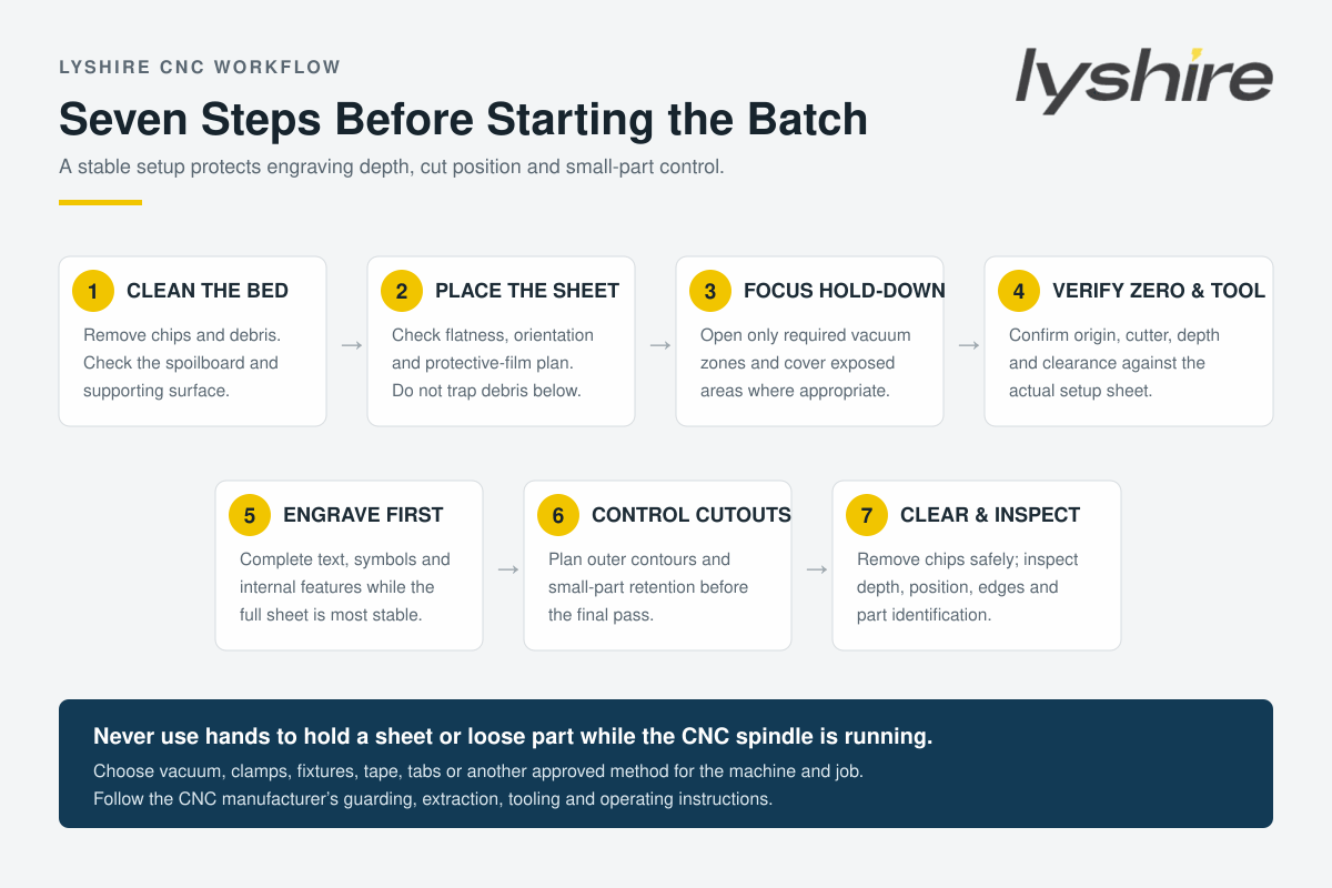
Quick answer: clean and inspect the table, place the sheet without trapped debris, concentrate hold-down under the active area, verify the tool and Z reference, engrave while the sheet is most stable, and plan how small parts will remain secured during final contour cutting. The best hold-down method depends on the machine, part geometry and production route.
Why workholding affects more than part position
An ABS engraving sheet is often only 1.3 mm or 1.5 mm thick, while the surface layer removed to expose the contrasting core is much thinner. If the sheet lifts, bows or shifts relative to the tool, the effective engraving depth can change across the panel. Fine text may reveal the core unevenly, holes may move from their intended position and an outer contour may no longer match the engraved artwork.
Workholding is therefore part of process control, not an afterthought. CNC manufacturer AXYZ notes that poor vacuum or air leakage can produce incorrect cutting depth, lost tolerances and material movement. Its technical guidance also emphasizes a clean sacrificial bed, controlled vacuum zones and removal of debris between the table and sheet.
This article focuses on efficient setup and processing sequence. Material quality requirements—such as approved color, thickness, surface condition and batch comparison—should still be defined in the drawing, specification, approved sample and purchase agreement.
Choose the hold-down method for the actual job
There is no single fixture that is correct for every CNC router, sheet size and part pattern. The operator should follow the machine manufacturer's approved methods and evaluate whether the job uses a full sheet, a partial sheet, large panels or many small labels.
| Hold-down route | Where it may fit | Points to control |
|---|---|---|
| Vacuum table | Full or larger sheet formats with enough covered area | Zone selection, spoilboard condition, leaks, exposed table area and part size |
| Low-profile mechanical clamps | Partial sheets, blanks or machines without sufficient vacuum | Tool clearance, sheet distortion, clamp position and collision prevention |
| Fixture or locating pins | Repeat parts and controlled blank sizes | Repeatable origin, clearance, pin position and drawing consistency |
| Approved tape or carrier method | Small parts or secondary support where appropriate | Adhesive residue, surface protection, removal force and machine compatibility |
| Tabs or an onion-skin strategy | Nested small parts where supported by the CAM and finishing plan | Tab position, remaining material, final separation and edge-finishing labor |
Vacuum tables are common in nested sheet production because the material can be held without clamps crossing the toolpath. AXYZ explains that a pump is generally suited to non-porous materials, with airflow passing through a sacrificial bed and vacuum zones concentrating suction in the active area. Actual equipment design varies, so operators should use the machine manual rather than copying another shop's setup.
Step 1: prepare the spoilboard and machine bed
Remove chips, dust, offcuts and adhesive residue before placing the ABS engraving sheet. Even small debris can create a local high point, prevent full surface contact or allow vacuum leakage. Check the spoilboard for heavy cut marks, damaged zones or a surface that is no longer level enough for the intended engraving depth.
AXYZ recommends maintaining and periodically skimming a fixed sacrificial bed so that the Z-axis reference and vacuum performance remain reliable. The appropriate maintenance interval depends on the workload, tooling and machine. Do not copy a fixed schedule without considering the actual condition of the bed.
Step 2: inspect sheet placement and orientation
Before starting the vacuum or clamps, verify that the sheet lies in the intended orientation and that the correct face is upward. For two-ply ABS engraving sheets, the face/core direction determines the visible engraved color. Brushed or directional finishes also require a consistent grain direction across related parts.
Check whether protective film should remain during the selected operation. The answer depends on the exact material, film, tool and required surface. Film may protect the face during handling, but a damaged, lifting or unsuitable film can interfere with inspection or machining. Confirm the process during sampling instead of applying one rule to every product.
Step 3: concentrate vacuum under the active area
Open only the vacuum zones required for the sheet position and cover unused exposed areas where the equipment manufacturer recommends it. Large uncovered areas can reduce the effective hold-down available beneath the workpiece. If the sheet covers only part of a large table, zoning becomes particularly important.
After applying vacuum, check the sheet at several positions before running the program. A full sheet that feels secure near one corner may still lift near the center or opposite edge. Do not place hands near a running cutter to test or improve hold-down. Stop the machine and correct the fixture safely.
Step 4: verify origin, cutter and engraving depth
Confirm the correct tool, spindle direction, origin, safe height and Z reference against the setup sheet. The cutter geometry, sharpness and chip evacuation must match the ABS engraving configuration and desired detail. A worn tool can increase cutting force and heat, which may worsen burrs, pull small parts or produce inconsistent edges.
Set engraving depth through a representative test rather than relying only on the nominal face layer. The objective is to remove the face cleanly and reveal the core without cutting unnecessarily deep. Record the tool and accepted setting so that a repeat order does not begin with an uncontrolled setup.
Step 5: engrave before releasing the outer contours
When the job includes both engraving and profile cutting, complete text, graphics and internal identification while the workpiece is still part of the larger sheet whenever the part design and CAM strategy allow. The sheet normally has its greatest supported area before external contours separate individual pieces.
Internal holes and slots may also be processed before the final outside contour, but the correct order depends on tooling, chip flow and part geometry. Review the toolpath preview for collisions, unnecessary rapid moves, closely spaced start points and any sequence that could reduce hold-down too early.
Step 6: control small parts during final cutting
Small labels create a particular workholding challenge. As material is removed around a part, the remaining sealed area decreases and cutting force can move the part toward the tool. AXYZ specifically identifies worn spoilboards, excess open vacuum zones and chips under the sheet as causes of weak hold-down for small parts.
Depending on the machine and finishing plan, the production team may use concentrated vacuum, dedicated fixtures, approved tape or carrier methods, tabs, or a controlled remaining-skin strategy. Each option changes cycle time and finishing labor. Test whether the retained part can be separated without damaging the engraved face or edge.
Step 7: manage chips and inspect the batch
Effective chip extraction helps keep the cutter path visible and reduces the chance that debris accumulates under later sheets. Follow the router manufacturer's extraction and guarding requirements. Never clear chips by hand while the spindle is turning.
After machining, inspect representative parts for engraving contrast, consistent depth, position, edge quality, hole size, remaining tabs, scratches and correct face/core direction. Label color groups and variable-data batches immediately so that visually similar components are not mixed during packing.
How nesting can improve sheet use without sacrificing control
Nesting software can arrange multiple labels or panels on one sheet to improve material yield. MultiCam describes nesting as a way to reduce waste and maximize yield, while also noting that vacuum tables improve part hold-down and cutting accuracy. However, the tightest possible nest is not automatically the best production nest.
Leave enough clearance for the cutter, chip evacuation, tabs and stable material between neighboring parts. Avoid layouts that create long unsupported strips or release a large number of tiny parts before the program finishes. Group identical tools and operations when this reduces changes without compromising part stability.
A repeatable setup record for production teams
A simple setup record can reduce dependence on one operator's memory. Record the sheet model, face/core orientation, thickness, sheet format, tool identification, engraving depth, feeds and speeds, origin, hold-down method, active vacuum zones, protective-film decision, toolpath sequence and accepted sample.
For LYSHIRE orders, common ABS engraving thicknesses include 1.3 mm and 1.5 mm, while other regular and project thicknesses are available. The exact size and tolerance must be taken from the selected product specification; one technical data sheet should not be applied automatically to every construction.
The standard ABS route is intended for CNC routing, rotary engraving, drilling and sawing. CO2 laser projects should use the separate PMMA/acrylic laser configuration. For a broader material-selection explanation, review the LYSHIRE processing system and engraving sheet structure system.
Problems that often point back to setup
| Observed problem | Setup items to review |
|---|---|
| Engraving depth changes across the sheet | Bed level, trapped debris, sheet flatness, Z reference, tool condition and fixture pressure |
| Outer profile shifts from engraved text | Vacuum leakage, clamp movement, cut order, tool force and small-part retention |
| Small labels move during the final pass | Active zones, spoilboard condition, exposed area, tabs/carrier method and remaining sealed area |
| Edges show burrs or heat | Tool sharpness, cutter geometry, spindle/feed combination, chip evacuation and number of passes |
| Scratches appear after machining | Table cleanliness, chip removal, stacking, film condition and part-separation method |
| Repeat batch requires excessive adjustment | Missing setup record, different tool, unverified material, changed origin, bed condition or fixture placement |
Operator safety: never hold the sheet or a loose component by hand while the CNC spindle is running. Use an approved vacuum, clamp, fixture, carrier, tab or other controlled method, and follow the machine manufacturer's guarding and operating instructions.
RFQ information for CNC-ready ABS engraving sheets
Tell LYSHIRE the CNC or rotary process, face/core colors, finish, thickness, full-sheet or finished-part format, artwork, smallest text, holes, outer profiles, backing, quantity and packing requirements. If the project has a defined flatness, thickness or surface acceptance requirement, include it in the drawing or specification.
LYSHIRE's standard MOQ is 500 sheets and standard colors may be mixed subject to order confirmation, availability and packing multiples. Buyers requesting custom cuts or finished parts should also provide the nesting priority, part identification and acceptable tab or carrier-removal method.
Frequently Asked Questions
Is a vacuum table required for every ABS engraving sheet?
No. Vacuum is common for sheet processing, but clamps, fixtures, approved tape/carrier methods or other solutions may fit particular machines and parts. Follow the machine supplier's guidance.
Why should engraving normally be completed before the outer contour?
The part usually has more supported area while it remains connected to the sheet. The final sequence must still be verified for the actual geometry, tooling and CAM strategy.
How can small parts be kept from moving?
Review vacuum zoning, spoilboard condition, exposed areas and debris first. Depending on the job, fixtures, carriers, tabs or a controlled remaining-skin method may provide additional retention.
Should protective film stay on during CNC engraving?
It depends on the exact material, film and operation. Test whether the film protects the surface without lifting, wrapping around the tool or hiding defects.
Can one setup be reused for 1.3 mm and 1.5 mm sheets?
Do not assume so. Recheck the Z reference, depth, cut-through strategy, fixture and toolpath for the selected thickness.
Can standard ABS engraving sheets be processed with a CO2 laser?
LYSHIRE's standard ABS configuration belongs to the CNC/rotary route. CO2 laser projects should use the separate PMMA/acrylic-based laser configuration.
Prepare an ABS CNC Sheet Request
Send LYSHIRE the machine, material colors, thickness, artwork, finished format, quantity and workholding constraints. The technical team can review the relevant ABS configuration and sample route.
Contact LYSHIRECNC workholding references: AXYZ vacuum-bed guidance, AXYZ small-part hold-down guidance, AXYZ sacrificial-bed maintenance and MultiCam nesting and vacuum-table overview.